
After trying everything I could think of in Illustrator and Inkspace, I finally opened up a text editor and edited the SVG file to change (in the header) from 100% to 200% which sized my board correctly. No matter how I set the scale in Adobe Illustrator or Inkscape, it came out about 30mm when I loaded the image in the Fritzing part editor. I have a SunAir Board that measures 65mm square. The Big Red Block disappears! The Fritzing Board Scaling Problem Lesson: Connect all of your connections in the Fritzing part editor. Success! As with many of these problems, I felt rather stupid afterwards. I added it in Fritzing breadboard view and the big red block had disappeared and I had two connections.

I started wondering if Fritzing would show a red block if I had unconnected pins (46/48 in this example) and so I tried a two pin IC and connected two pins. I knew that SVG files have lots of graphic elements that are not pins (so Fritzing must handle this) and not a desired connector. I put on my thinking cap (made of tin foil, of course) and noticed that the color for unconnected was red and I wondered if some graphic was covering the whole board. There was nothing on the web about this, except one obscure reference with no answer. I spend the next 20 hours trying to track down what had gone wrong with Eagle, Inkscape, Adobe Illustrator and Fritzing. I wanted to see if the part is the right size and how it looks in the Fritzing Breadboard view, so I connected two of the 48 connections and then added it into the Breadboard view. I exported the SVG graphics from Eagle using an ULP and ultimately brought the graphics into the Fritzing part editor. I was building a 48 connector Fritzing model for the upcoming SwitchDoc Labs product SunAir (a Solar Power controller / sun tracker and phone charger). I’m documenting them here to save others time that may be doing the same thing. Here are the three problems that cost me a lot of time in the process. I found the editor and process clumsy, but ultimately successful.

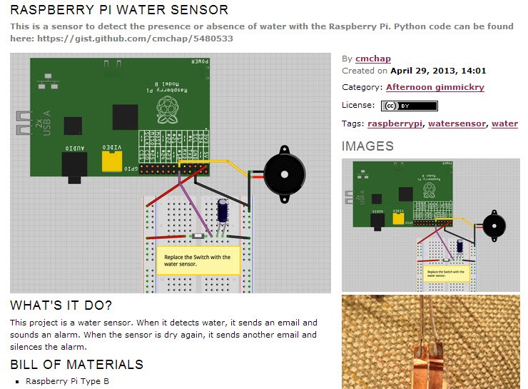
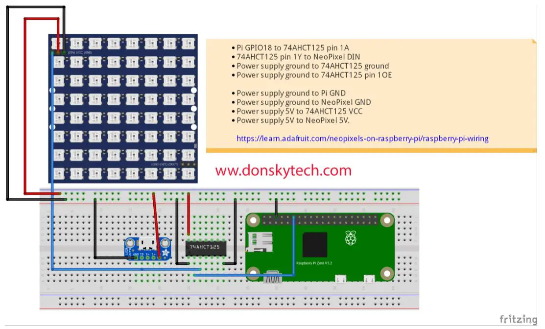
Here is a SparkFun Tutorial that does a pretty good job. The purpose of this note is to save others time with the Fritzing New Part Editing tool. I like schematics, but I understand the value of these breadboard diagrams and add them to all of our documentation to help beginners over the hump of the learning curve.įor example, here is a Fritzing diagram for the SwitchDoc Labs External WatchDog Timer: External WatchDog Timer Connection to Raspberry Pi B+ Fritzing diagrams do make it easier to build breadboards using extant products.

Problems: New Part Generation with Fritzingįritzing ( ) is an open source design package that makes electronics more available and readable, especially for the beginner and maker.


 0 kommentar(er)
